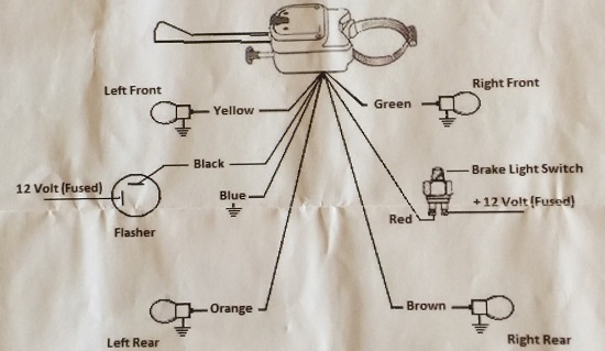
Driving safety is paramount, and proper signaling on the road ensures not only your safety but also that of others around you. Installing a turn signal switch is an essential aspect of vehicle maintenance, and understanding how to wire it correctly is crucial. In this guide, we’ll delve into the intricacies of wiring a 7 Wire Universal Turn Signal Switch Wiring Diagram. Whether you’re upgrading an old switch or customizing your vehicle, this comprehensive tutorial will help you navigate the wiring process with confidence.
Understanding the Basics:
Before diving into the wiring process, let’s familiarize ourselves with the components of a 7-wire universal turn signal switch. These switches typically have seven wires for various functions: left turn signal, right turn signal, brake lights, battery positive, ground, and indicator lights for the left and right signals. Each wire serves a specific purpose in the signaling system, allowing you to control your vehicle’s lights effectively.
Tools and Materials:
Before you start wiring your turn signal switch, gather the necessary tools and materials:
- Wire cutters/strippers
- Electrical tape
- Soldering iron and solder (optional)
- Heat shrink tubing (optional)
- Wiring diagram specific to your vehicle and switch model
Wiring Process:
Preparation:
Begin by disconnecting the vehicle’s battery to avoid any electrical accidents. Lay out your tools and materials in a well-lit workspace, ensuring easy access to the wiring harness and switch location.
Identify Wires:
Refer to the wiring diagram provided with your turn signal switch to identify each wire’s function. Typically, the wires are color-coded, but it’s essential to double-check their purpose to ensure correct connections.
Battery Connection:
Connect one wire from the battery positive terminal to the input terminal of the turn signal switch (often labeled “BAT”). Use a suitable gauge wire to handle the current safely.
Ground Connection:
Connect one wire from the battery negative terminal to the ground terminal of the turn signal switch (often labeled “GND”). Ensure a solid ground connection to prevent electrical issues.
Turn Signal Wiring:
Connect the left turn signal wire from your vehicle’s wiring harness to the “L” output terminal of the turn signal switch. Similarly, connect the right turn signal wire to the “R” output terminal.
Brake Light Wiring:
Connect the wire from your vehicle’s brake light circuit to the brake light input terminal of the turn signal switch. This allows the brake lights to override the turn signals when activated.
Indicator Lights:
Connect one wire from the left turn signal indicator light to the output terminal for the left turn signal on the switch. Repeat the same process for the right turn signal indicator light.
Testing:
Once all connections are made, reattach the vehicle’s battery and test the turn signal switch. Activate the turn signals and brake lights to ensure they function correctly. If necessary, troubleshoot any issues before finalizing the installation.
Safety Tips:
Always follow the manufacturer’s instructions and wiring diagram for your specific turn signal switch model.
Double-check all connections before reattaching the battery to avoid electrical hazards.
Use proper insulation techniques such as electrical tape or heat shrink tubing to protect exposed wires and prevent short circuits.
Conclusion:
A properly wired turn signal switch is essential for safe and efficient signaling on the road. By following this comprehensive guide, you can confidently install a 7-wire universal turn signal switch in your vehicle. Remember to prioritize safety, double-check your connections, and test the functionality before hitting the road. With your signaling system in top condition, you can navigate with confidence, ensuring a smoother and safer driving experience for you and those around you.
